
On-Site Acoustic Testing provides field verification of RF shielding installations, including visual inspection, electrical continuity testing and RF attenuation testing. Testing can be performed during installation to identify defects while shielding materials remain accessible, as well as on substantially completed areas to verify required transmission-loss performance.
RF Shielding Installation and Electrical Continuity
For RF shielding to work correctly, all shielded surfaces must be electrically connected to each other and grounded to earth. In a five-sided shielded room, gaps between surfaces such as RF foil-shielded wall panels must be bridged with conductive material to maintain conductivity between panels.
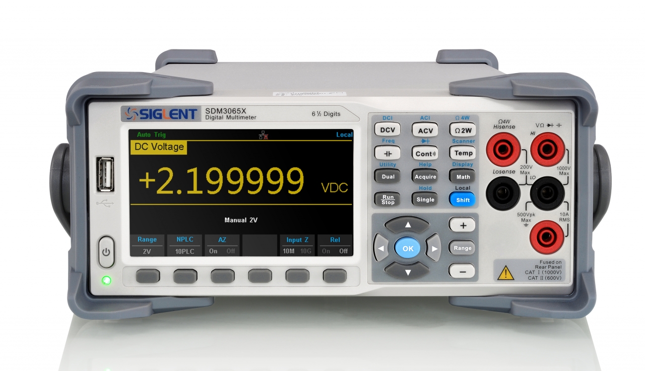
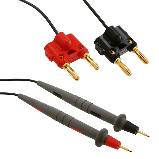
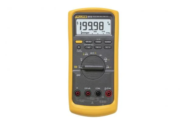
Continuity testing during installation field-verifies these connections by measuring DC resistance, in ohms, between adjacent surfaces. RF foil-shielded rooms may require many connections to earth ground, whereas metal RF-shielded enclosures may use a single grounding point.
RF Attenuation Testing During Construction
RF testing can be conducted on sufficiently large wall sections during installation in accordance with IEEE 299-2006 Annex E or another requested standard. This testing determines whether the shielding assembly provides the expected signal attenuation at the relevant frequencies.
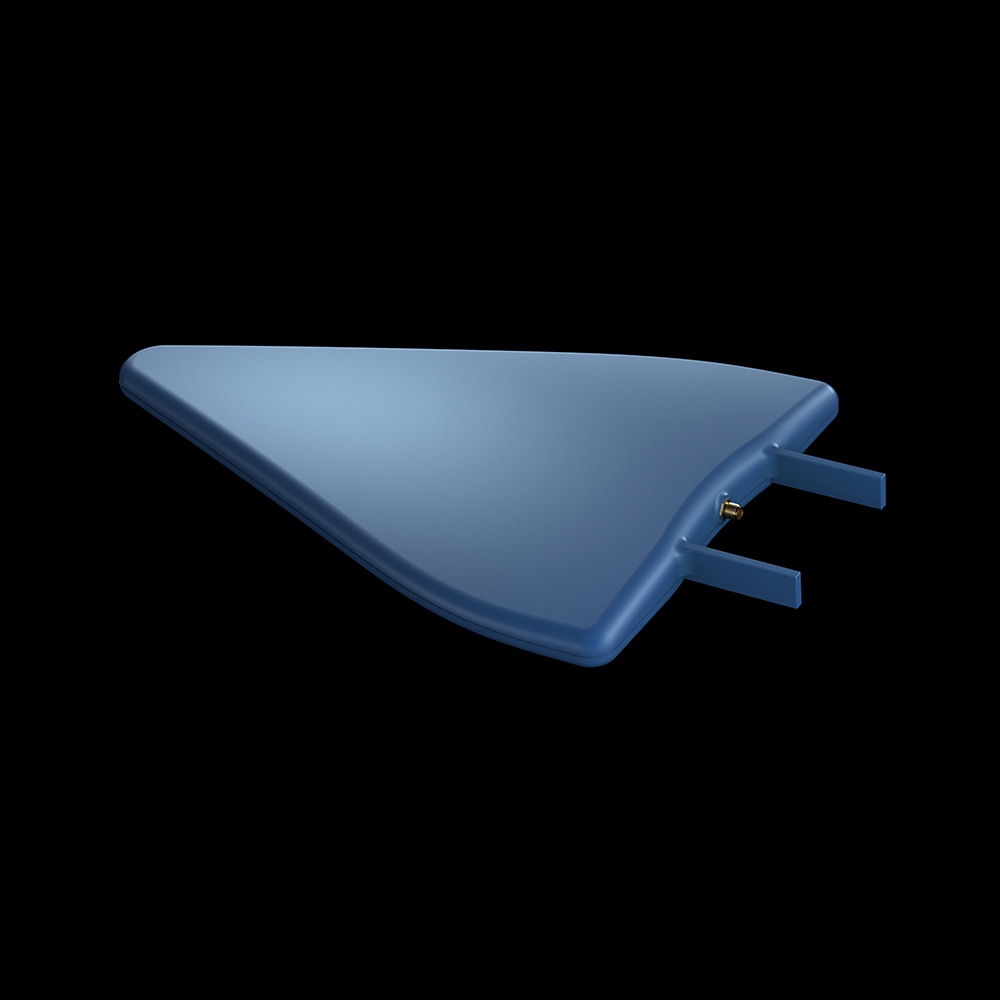
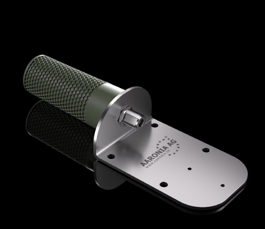
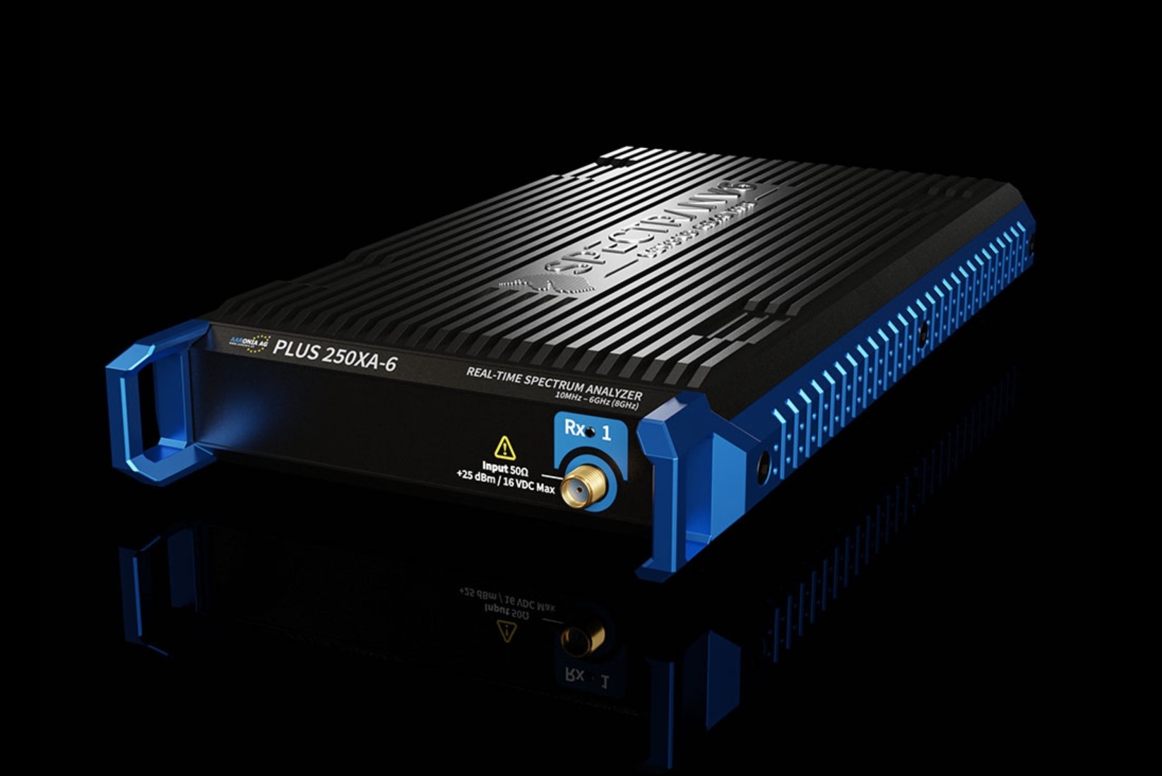
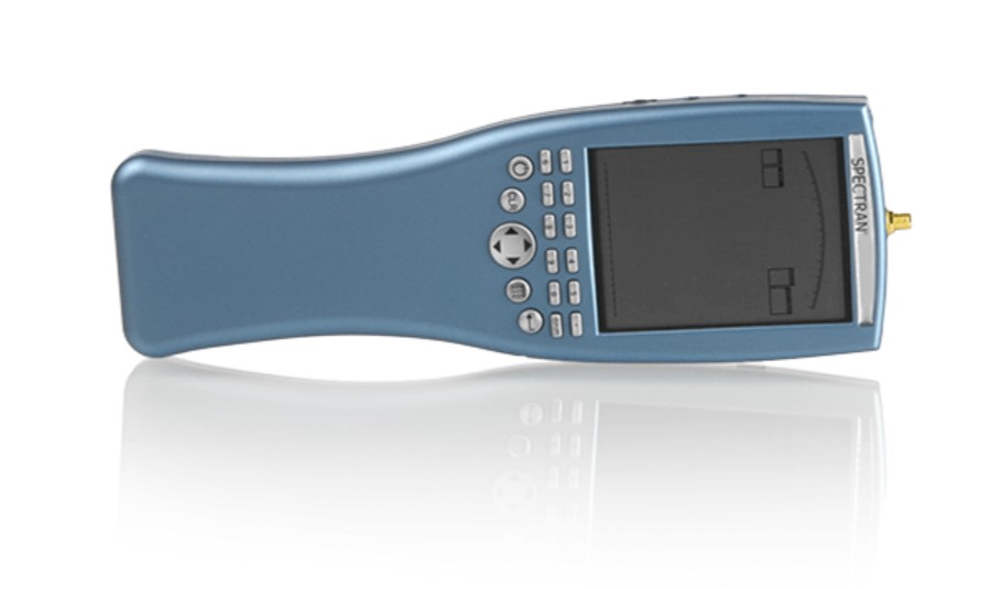
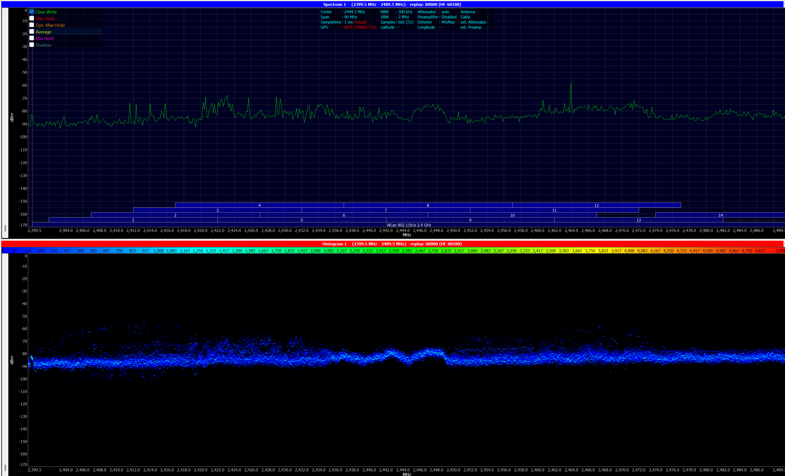
Continuity, SELDS and RF Attenuation Testing
Different test methods provide different information about an RF shielding installation. Continuity testing is typically used to verify installation details such as foil overlaps, corner details, door frames and other transitions. Resistance measurements between disparate elements indicate electrical continuity or reveal where continuity is lacking.
SELDS testing can be useful for certain applications, but its use is limited when evaluating large areas of RF foil shielding installed as part of a room. Large panel areas can act as antennas and radiate energy from edge surfaces, creating multiple electromagnetic fields that make isolation of seam leakage difficult. Commercially available SELDS equipment has therefore found greater acceptance for smaller, fully completed enclosures, including completed door, wall and ceiling penetrations.
Continuity alone does not establish RF attenuation performance. An installation can demonstrate excellent electrical continuity between elements while still providing substandard RF attenuation. Practical assessment of actual attenuation requires RF field testing using IEEE 299-2006 or another applicable RF field-testing protocol.
Initial Site Testing
An initial site-testing program can include the following activities:
Physical Examination of Seams and Material Joints
Installed RF foil shielding is examined for proper seam joining and appropriate adhesive-tape installation. Identified defects can be documented and submitted to the contractor for remediation.
Physical Examination of RF Foil Shielding
Installed shielding is examined for material integrity. Tears, scuffs, spider veins and other defects can be identified and documented for remediation.
Continuity Testing Between Panels and Material Joints
Joints between RF foil shielding, door frames, columns and other conductive elements are checked for acceptable continuity. Areas with resistance values above acceptable project limits can be identified and submitted for remediation.
RF Testing of Completed Areas
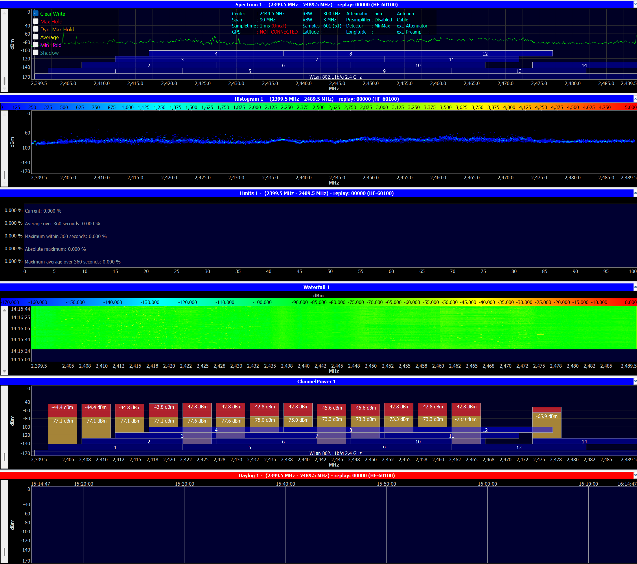
Substantially completed areas can be tested using RF test equipment to determine whether the shielding provides the required transmission loss at the relevant frequencies, in accordance with IEEE 299-2006 Annex E or another requested standard. Areas demonstrating sub-optimal transmission loss can be identified for remediation.
Independent Field Verification
Testing during construction gives contractors and project teams an opportunity to identify installation defects before shielding materials become inaccessible. Final RF attenuation testing then provides direct field measurement of the completed shielding performance.
Contact On-Site Acoustic Testing to discuss RF shielding inspection, continuity testing or RF attenuation testing requirements for your project.
Discuss Your RF Shielding Project
Tell us about the facility, shielding system, project stage and testing requirements. We can discuss an appropriate field-verification approach.
